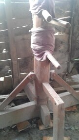
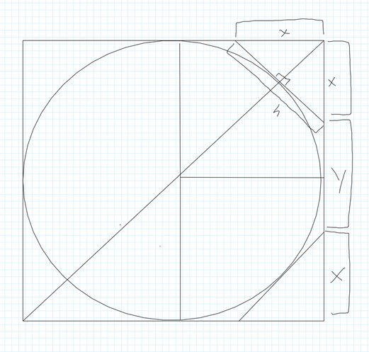
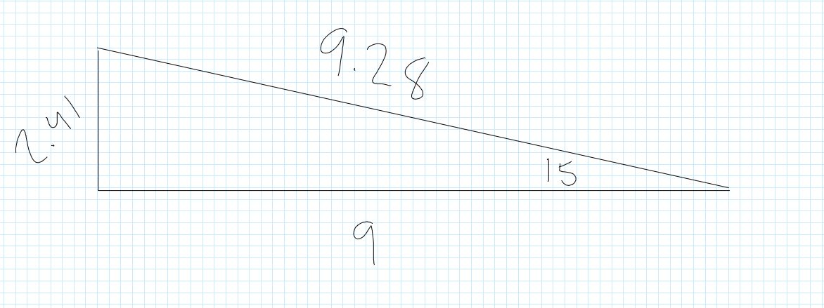
 What It Is And Where It Came From A Wing Chun Dummy (or Muk Yan Jong, “Wooden Man Post”) is a traditional Chinese kung fu training instrument popularized by Ip Man and the Wing Chun school of kung fu. In its typical form, it has a large vertical post with two arms emerging at offset angles, a single arm set straight out from the post, and a bent-L-shaped leg near the base. This design is intended to roughly simulate the form of a human opponent and allow a kung fu student to practice techniques under conditions with physical resistance and feedback. 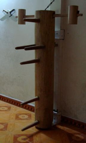 Although the modern form was popularized by Ip Man and the Wing Chun school of kung fu in the twentieth century, wooden dummies like it have existed for much longer. Legendary origins go back to the Shaolin temple, with a variety of stories and actual artifacts spanning past centuries. Different designs would use a different base or frame mechanism to secure the post, and different numbers or types of arms and legs. One key feature of the base/frame mechanism seems to have been some kind of slight flexibility or “give” so that, when struck, the dummy would respond similarly to a human opponent. One historical solution was to sink the post into an oversized hole in the ground and fill the hole with plant fibers or gravel. The modern design uses a frame with two relatively narrow struts placed horizontally through or behind the post and secured to a wall or a larger frame. Ip Man apparently favored this design.  Build Instructions I decided to build my own since retail dummies are somewhat expensive. You can watch the full process here; on this blog post I’ll show diagrams and formulas that will be helpful. I used these instructions but they are inspecific on several important details. I’ll mostly limit my explanation here to those things not explained well or included in that linked PDF, since they are quite good and a great starting point. Body/Post After a little research, I learned that it would be both more difficult and more expensive to buy an actual post, so I decided to build a post by laminating boards together and truncating the edges. The final dimensions of the post should be 5’ tall and 9” in diameter. I glued six ten-foot 2x10s together with Wood Titebond 3, cut the post down to 5’, and then set to work making it in an octagon. In theory six 2x10s should make a block 12 inches by 10 inches. However, the stated dimensions of lumber are larger than the actual dimensions. A 2x10 is actually more like a 1½ by 9¼. Six added together make a 9x9¼ square post—an acceptable level of precision to me. Now, how to make it an octagon with even sides? Imagine a cross section of the square post. I’ve inscribed a circle with diameter and radius lines and a diagonal line from corner to corner for reference. What interests us is the corner specifically. If a line is drawn tangentially to the circle, we create a triangle that, if cut off from the square post, will create a perfect octagon. That triangle has one side ‘h’ and two sides ‘x’. If we find the value of ‘x’, we can know where to begin the truncating cut. Notice that each side of the square must be 2 ’x’ plus some other value. We’ll define it as ‘y’. Notice also that ‘y’ must be the value of ‘h’, since we are trying to create a perfect octagon. A little bit of geometry and I cam out with the numbers x = 2.64” and y = 3.72”. I converted those from decimal to imperial as 2⅝” and 3¾”. The angle of the cut, of course, is 45 degrees (half of a 90 degree square angle); I used a handheld circular saw. The final product is a 5’ tall pillar in the shape of an octagon. Arms I built the arms out of 4x4s. The length of the 4x4 is defined in the following way: the arm typically extends out from the body about 12”, plus another ~9” are required for the shaft through the body. I rounded up to ~24 inches and I would recommend doing so; you can always cut it shorter but you can’t cut it longer. The shank of each arm is 1.5 inches square and that is simple enough to do: measure 1.5 inches and cut with a band saw, jig saw, etc. The arm itself is a little trickier as it is circular and ideally should taper. A taper (and a cylindrical shape) can be achieved in a similar way that the post was turned into an octagon. Referring to the cross-section of the post above, but treating it as a cross-section of the arm, use the following equations: x/y = 0.71 2x + y = length of square side The two equations can be used in conjunction to generate measurements for an octagon out of any square pillar. In this case we have a 2.5” diameter root of the arm and a 1.5” diameter tip. We can treat both those measurements as the length of the square sides, and using the equations above, we get approximately x = ¾” and y = 1” for the root and x = 7/16” and y = ⅝” for the tip. Marking this on each arm and drawing lines from root to tip gives us a diagram like this on each side of the square arm 4x4: Simply cut in a similar way to the post, but following the taper, and you have an octagonal tapering arm. Sand to your preferred smoothness. Remember to cut the shank offset to the side on two of the arms and dead center on the third arm! This is illustrated well in the PDF linked at the beginning of the instructions on this blog post. Legs The instructions are given in the PDF linked earlier. I glued the pieces together with Wood Titebond III. I built the leg with an extra long shank and extra long leg piece so that I could manually cut it to size later using trial and error. 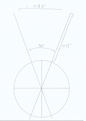 Post Holes Cutting four holes in the post was probably the trickiest part of the whole project. The center arm hole is fairly simple and its illustrated well in the PDF mentioned above. The offset arms and the legs are significantly more difficult because of their angles. At what angle should the offset arms be placed? According to the PDF mentioned above the tips of the offset arms should be ~8.5” apart. We also know that the arms themselves are about 16.5” from their tips to where they cross at the center of the post (12” + 4.5”). After some geometry I got 30 degrees from one arm to the other, or 15 degrees from the center to each arm. The linked PDF describes an excellent way to make a homemade protractor. Once you’ve done this, you can easily measure ~30 degrees on the front of the dummy and use the protractor to mark the holes on the back side. Alternately, if your protractor is long enough, you can simply measure the 8.5” distance between the protractor arms at 12” out from the body and use that angle. The leg hole should be similarly angled at about 15 degrees. Instead of using the protractor, I calculated this using the Pythagorean theorem and verified it with a sin() calculation. So, 2.41” up from the level of the hole in the front is the hole in the back. From here it was just a question of gouging and drilling the holes as I had marked them. It took a long time, but worked fairly well. Remember that the holes should be slightly larger than the arm/leg shanks so that they can be easily inserted and shift a little during practice.
Base The base is fairly self-explanatory if you watch the attached video; it’s simply a set of 2x4s laid crossways into a crosshatch formation. Remember that the dimensions of a 2x4 are closer 1½” to 3½” and cut them accordingly. Conclusion So, there you have it. Total cost was about $70 in lumber (the 2x4s and 4x4s were scrap) and ~$15 in glue. Not bad at all compared to the retail price of these things, even if I had had to buy extra lumber. If anything is unclear leave a comment below and I’ll try to clear it up. I won’t include any drills here, but it’s easy to find basic drills to practice on your newly built dummy. Happy building and practicing! JF
2 Comments
Sean Ferrell
4/19/2022 09:35:19 am
all I wanted was to file an extension! Your system did did not accomplish this!
Reply
Leave a Reply. |

 RSS Feed
